The Other Lamp
**Updated 26 September 2020
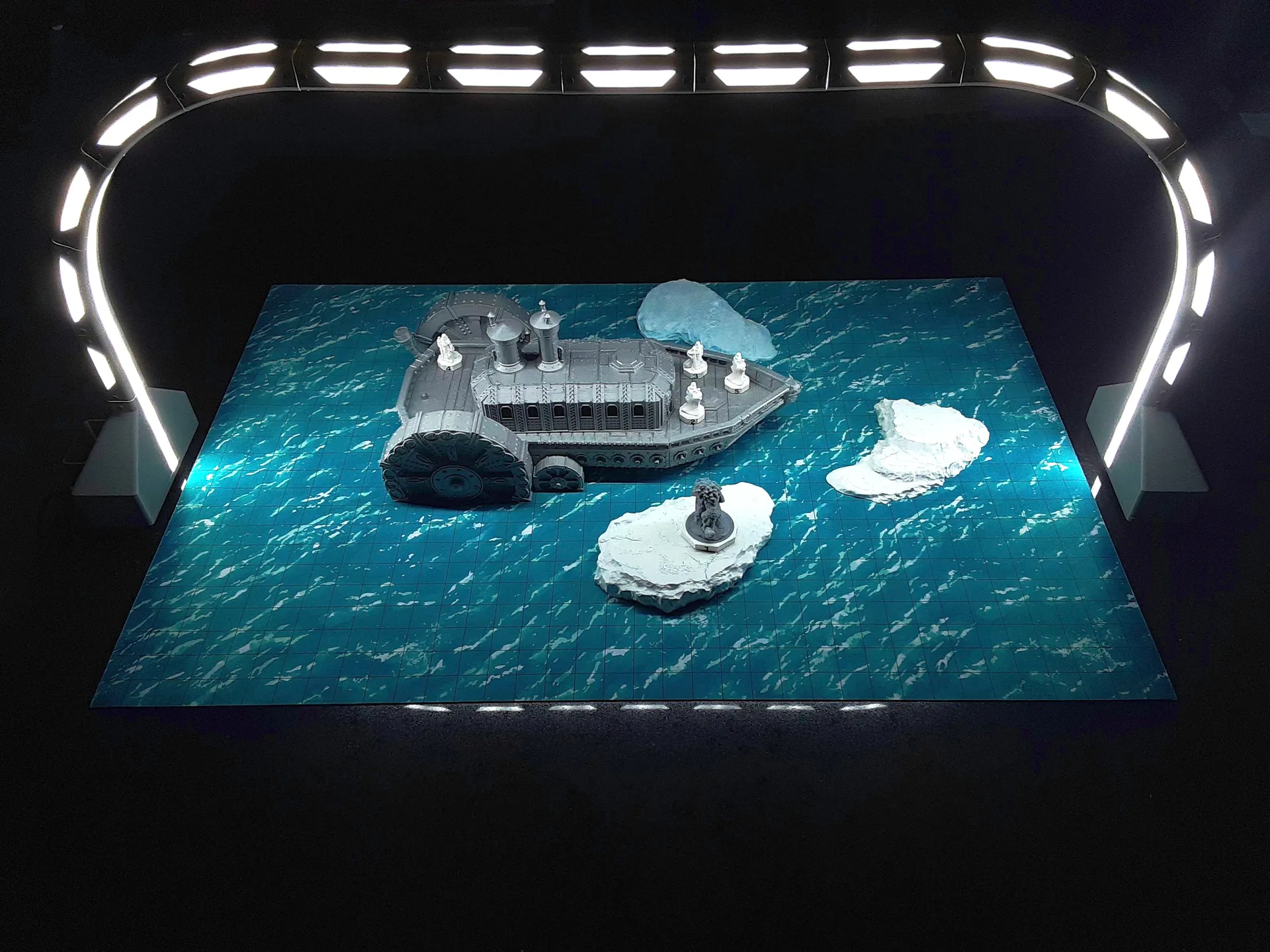
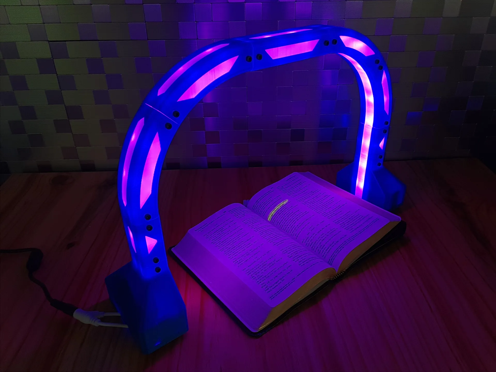
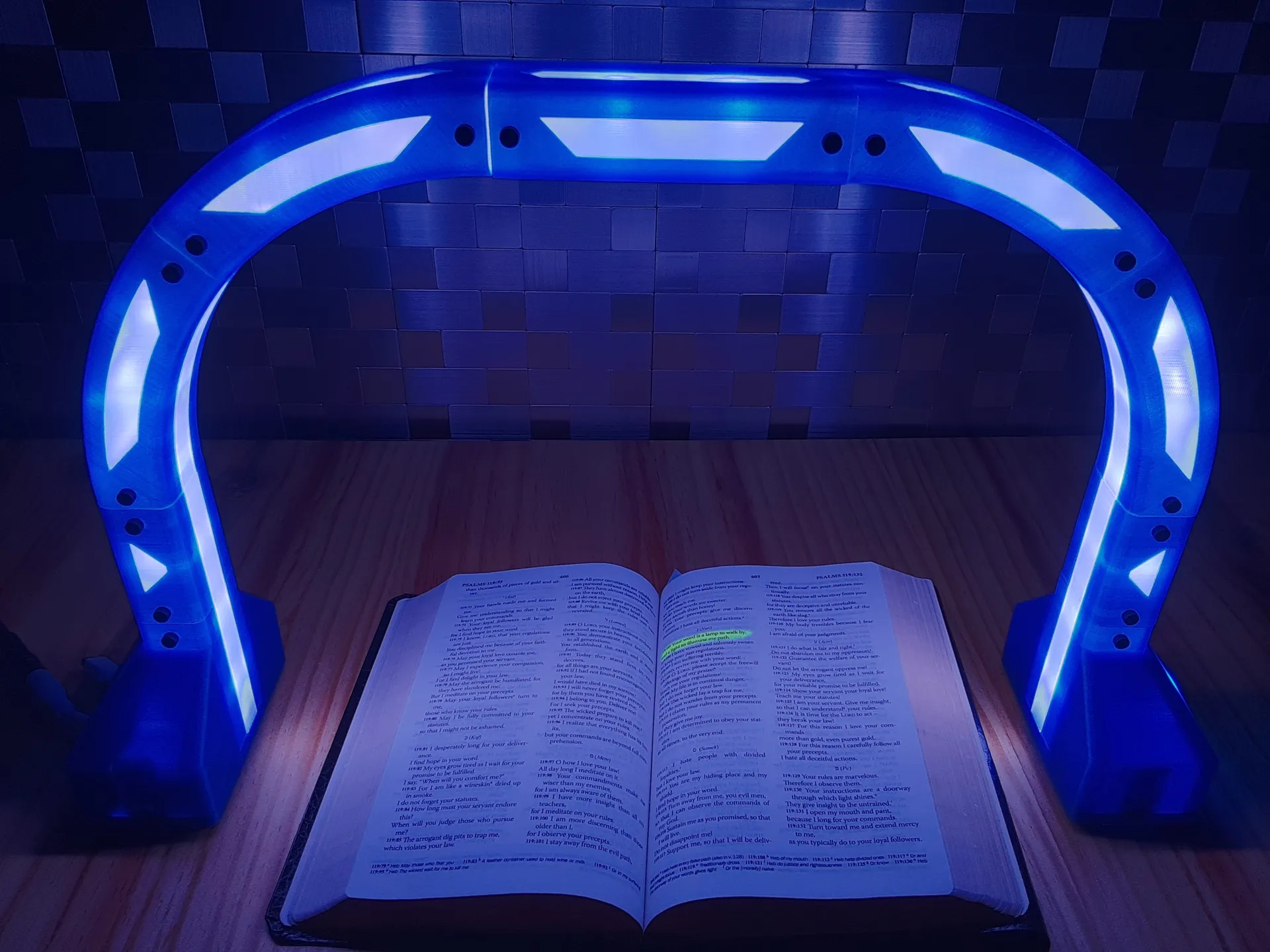
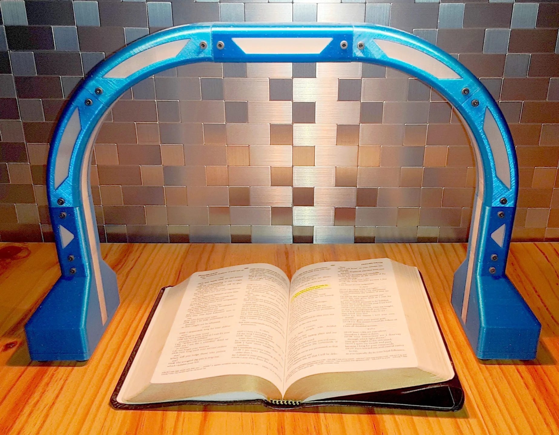
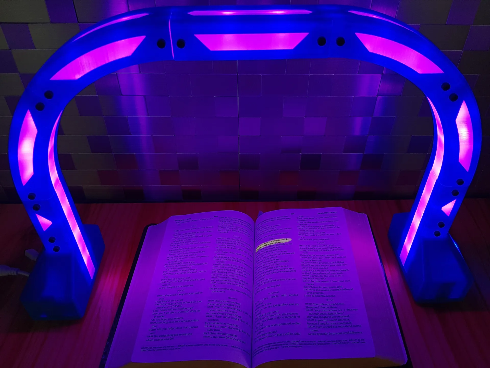
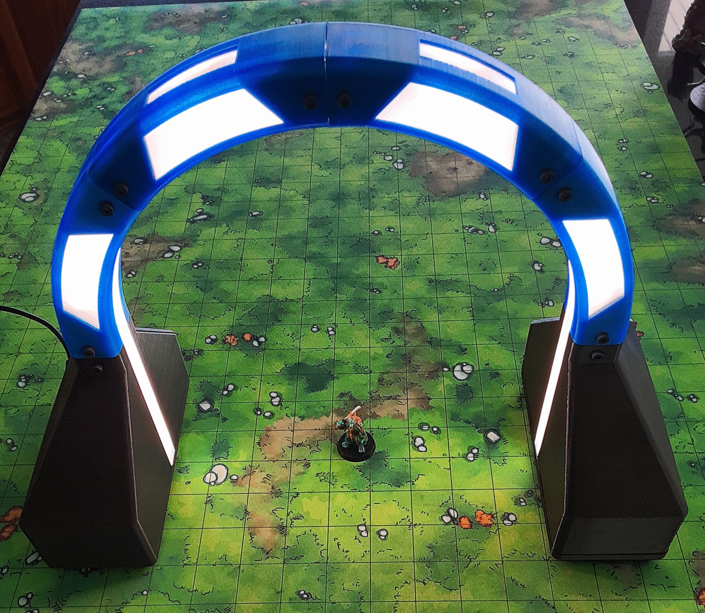
A modular, parametric, support free LED strip lamp for your 3d printer, desk, etc.
In the contest Lights and 3D printing
77
114
2
1727
updated August 28, 2020
Description
PDF**Updated 26 September 2020
A modular, parametric, support free LED strip lamp for your 3d printer, desk, etc.
Changelog:
26 September 2020:
</ul>
</ul>
</ul>
Why I named it the "Other Lamp":
I chose this name in reference to Psalm 119:105 "Your word is a lamp to my feet and a light to my path." (ESV)
Inspiration: Led bridge lamp Universal Segment by Opossums
An amazing project that I currently use on my desk, but too large for my printers, and not optimized for printing and easy assembly. So I started from scratch to design a parametric file that produced an simple print that could be easily assembled.
Required hardware:
*optional
- M3 x 10mm screw: 4 for each segment and base printed
- M3 square nut: 4 for each segment and base printed
</ul>
</ul>
Features:
- Rigid (no flex when stretching across a long desk)
- Connected by screws (secure connection that also allows disassembly for easy adaptability to a different space, or for easy transport)
- Absolutely *0 supports required* (waste of time to remove and can leave ugly scars, and waste of money from the extra filament and print time)
- Minimum bridging (maximum length is currently across the with of the square nut used)
- Easily oriented in slicer
- Custom channel for different sized led strips (would work with rgb, rgb+w, rgb+cct, single color)
- Gap between the led strip and front of the diffuser to minimize 'spotty' look of the leds
- Minimum use of filament (save time/money)
- Space for electronics (I wanted to be able to install a zigbee controller for an rgb+cct led strip for easy home automation or a manual dimmer for a single color led strip)
- Easy assembly
- Modular
- Ability to extend vertically and horizontally
- Compatible with multiple 3d printing technologies (fdm, sla, etc.)
- compatible with as many materials as possible (petg, resin, etc.)
- Scalable (anything from 1/2 foot to 5+ feet)
- Aesthetically pleasing
- LEDs extend all the way to table
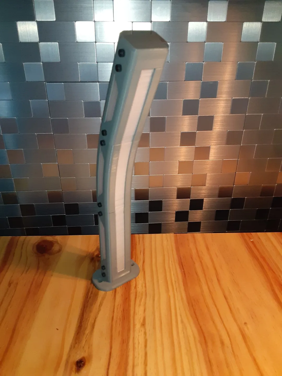
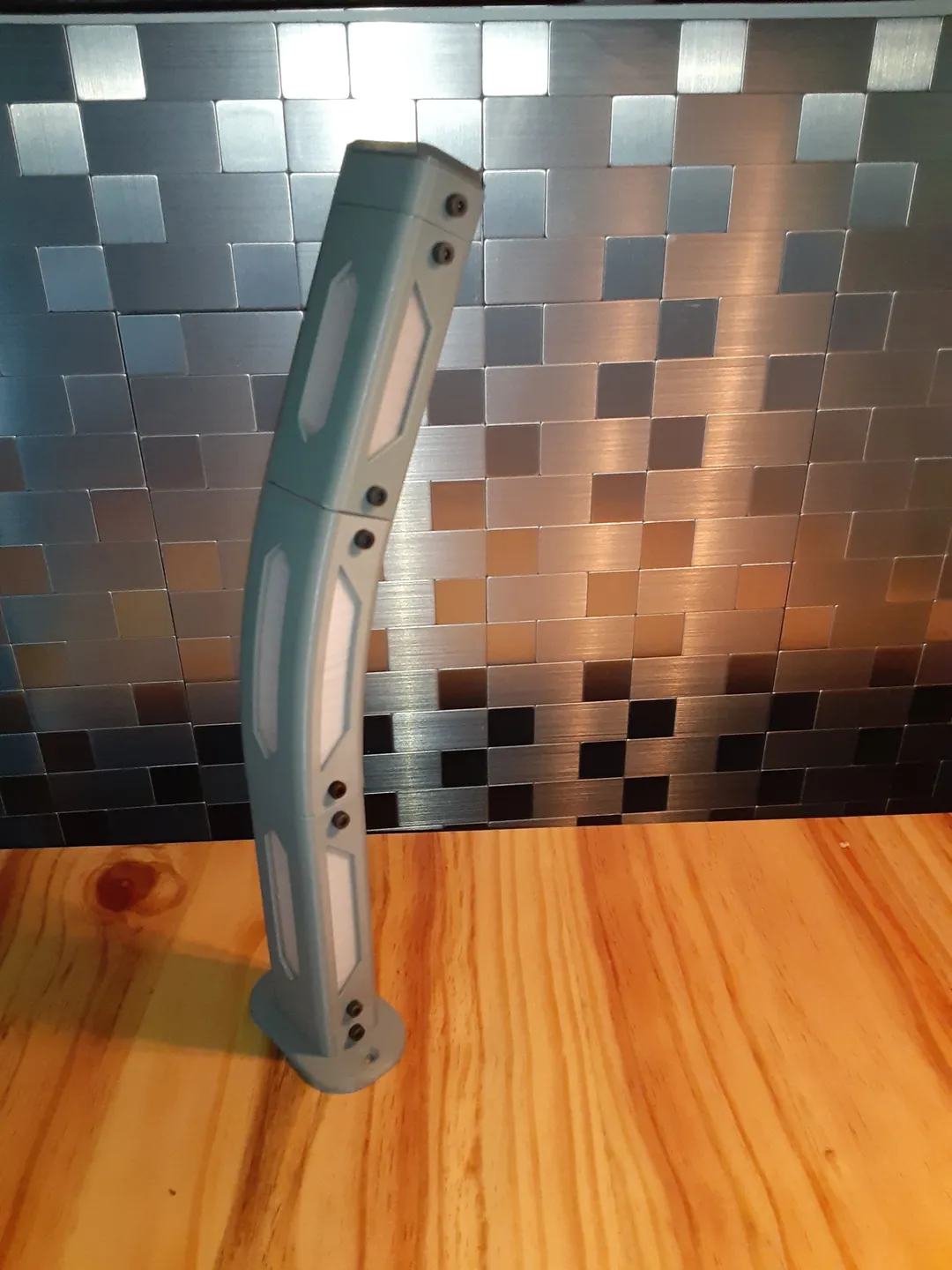
Prototypes:

Print instructions
Materials:
PETG or other higher heat resistant materials.
-
*PLA is not recommended. It would run the risk of deforming under heat of the LED strip in the diffuser, or any electronics used in the base.
What to print:
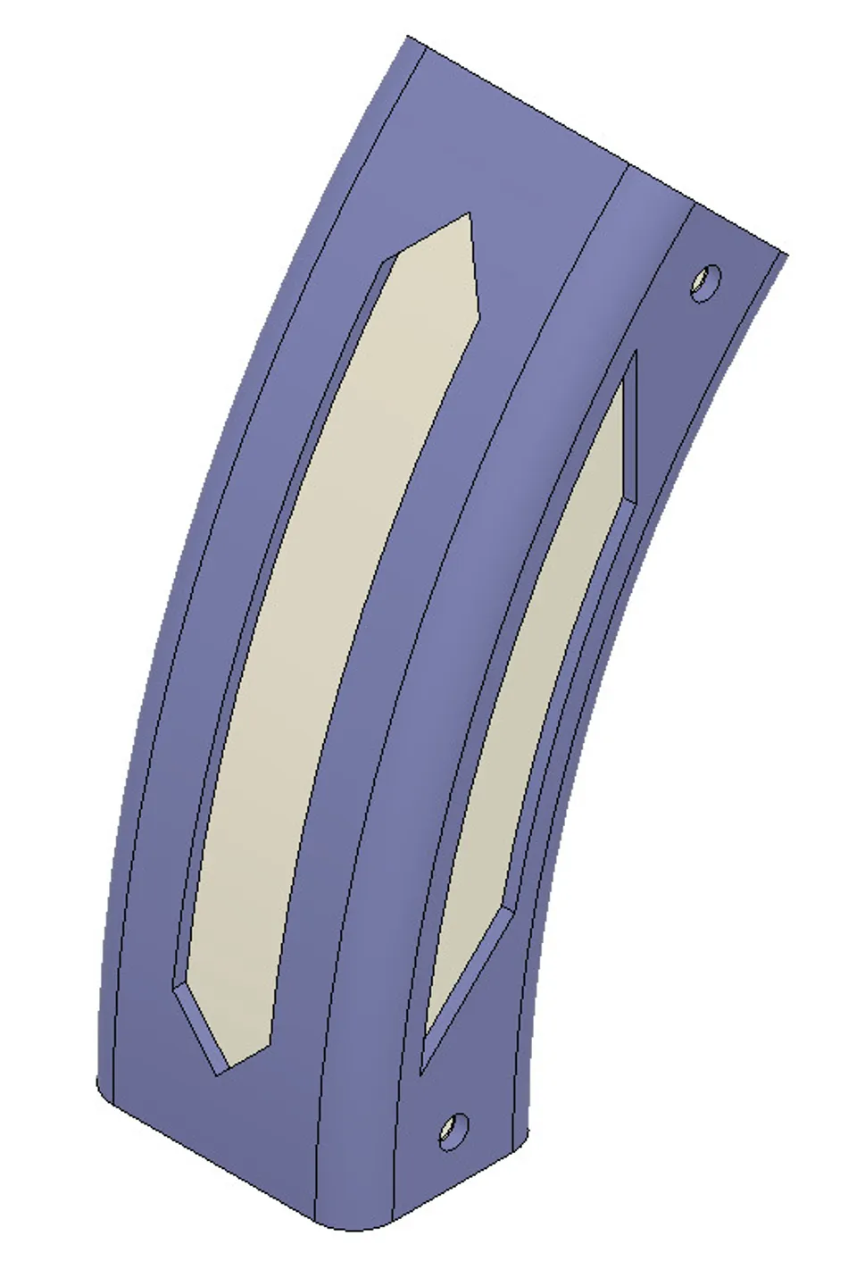
- 2 sets of 2_curved_segments_exterior
OR
3_curved_segments_exterior.- Choose 2_curved_segments if you want 2 curved pieces on each corner or choose 3_curved_segments if you want 3 curved pieces on each corner.
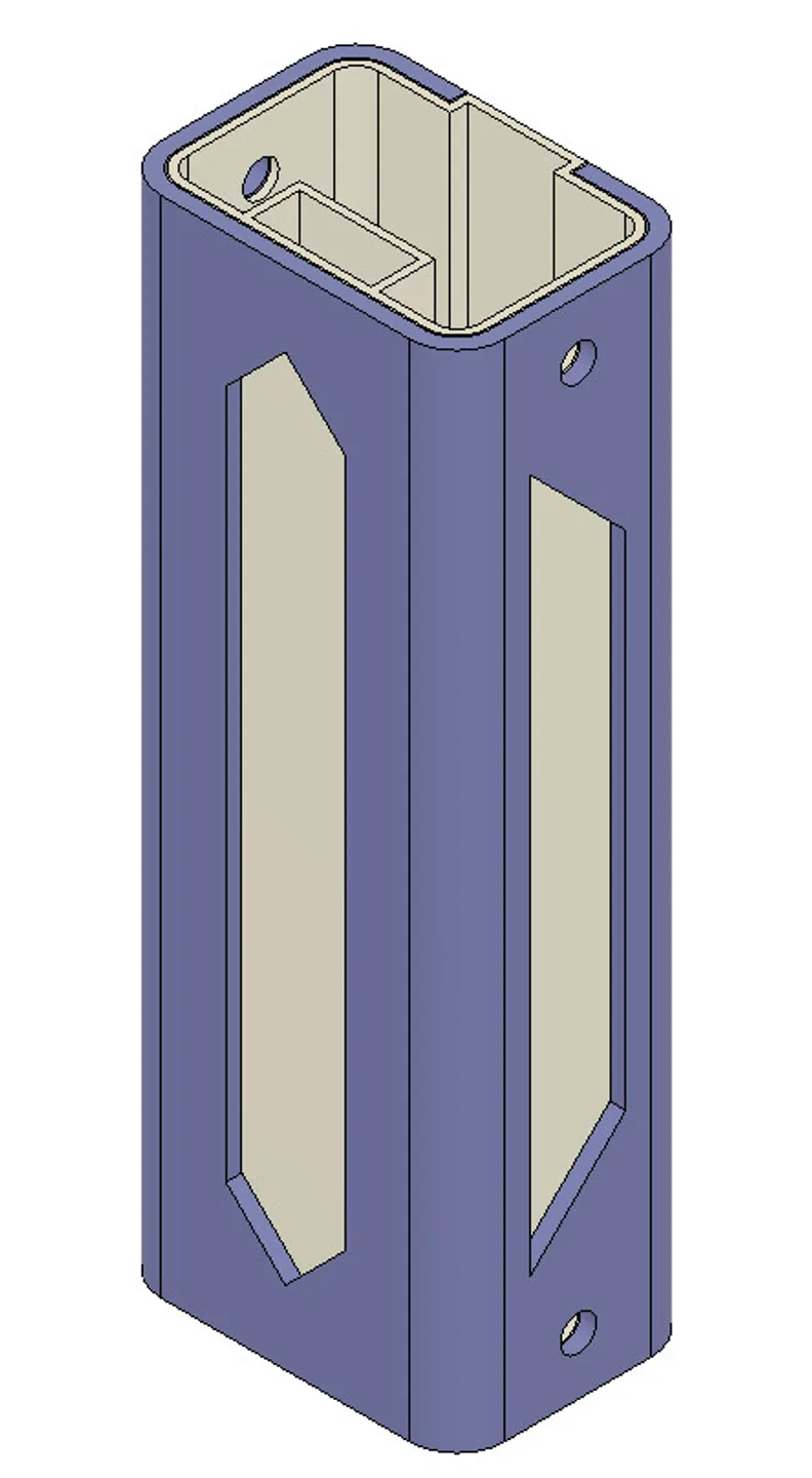
- Any number of the straight_50mm_exterior
OR
straight_100mm_exterior to reach desired height/width. - An equal number of diffusers as exteriors.
- Connectors. (Notice the small circle to signify that side connects to a curved segment, allows easier identification at a glance.)

- connectors_curved_to_curved connects curved segments.
- connectors_straight_to_curved connects curved segments to straight segments.
- connectors_straight_to_straight connects two straight segments.
- For large base:
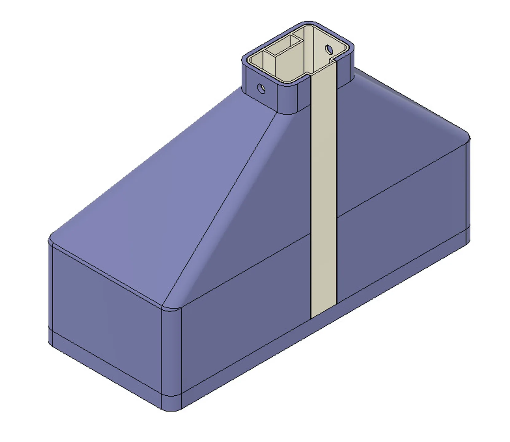
- base_large_exterior
- base_large_diffuser
- base_large_floor_with_bumper_cutouts
OR
base_large_floor_without_bumper_cutouts - Use the file with the bumper cutouts if you want to use the bumpers I linked above. If you don't want bumpers or want to use adhesive bumpers use the file without the bumper cutouts.
- For small base:
- base_small_exterior
- base_small_diffuser
- base_small_floor_with_bumper_cutouts
OR
base_small_floor_without_bumper_cutouts - Use the file with the bumper cutouts if you want to use the bumpers I linked above. If you don't want bumpers or want to use adhesive bumpers use the file without the bumper cutouts.
- For table mount: If you want to mount it to a table with electronics hidden under the table.
- table_mount
- If you only want to print a vertical piece, or half an arch, etc.:
- end_cap
Print settings:
- Supports: NONE (!!!)
- Nozzle size: .4mm
- Elephant foot compensation: 0.2
- Brim:
- Exterior/Diffuser/Base: Disabled (0mm)
- Connectors/Floor: Optional
- Perimeters: 3
- Wipe while retracting (Printer Settings>Extruder): disabled
- When printing the 45° overhang on the exterior windows the plastic would curl just enough to catch on the nozzle during the wipe, and due to the small surface area on the build plate pulled a few of my prints off the build plate. Disabling the wipe prevented this.
- Extrusion Width and Overlap (These are the default settings for Mk3s. Ensures that the exterior is exactly 4 perimeters, and the diffuser is exactly 2 perimeters)
- Perimeters: .45mm
- Infill/Perimeters overlap: 25%
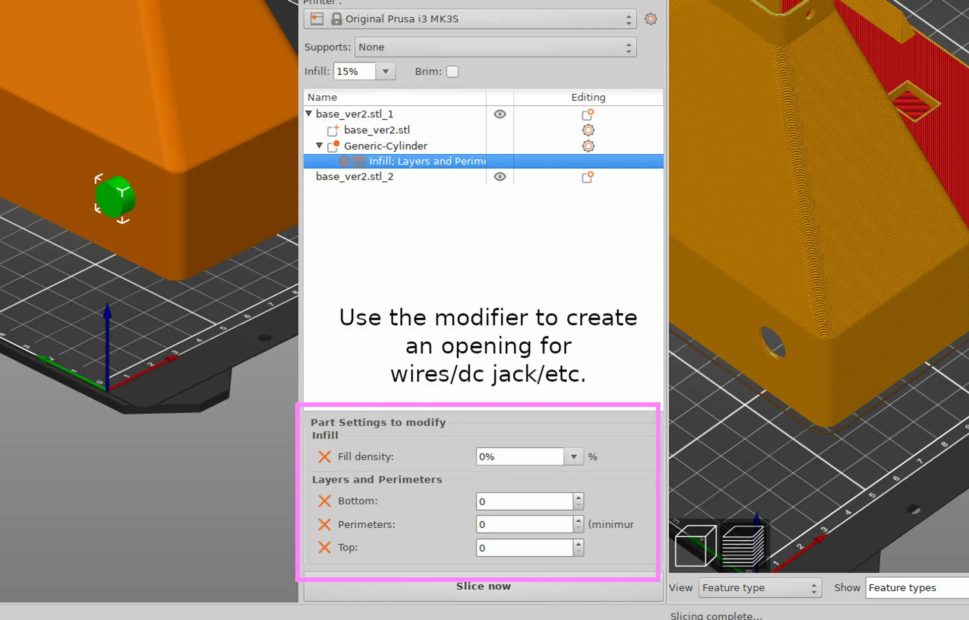
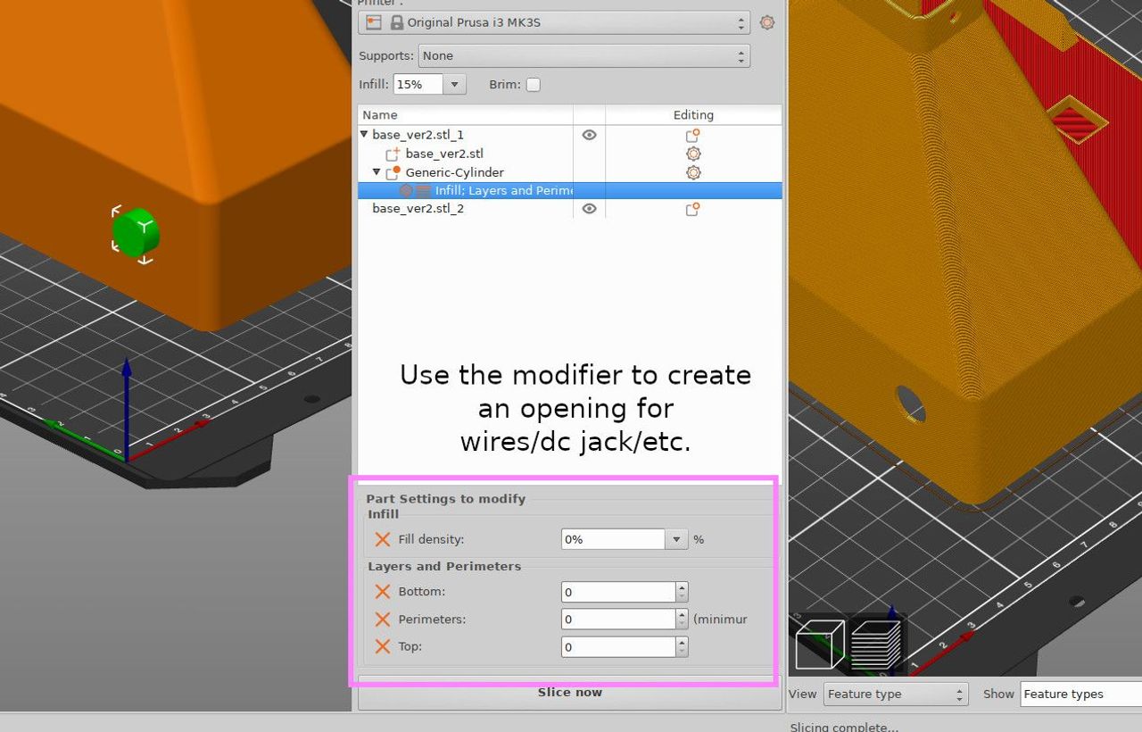
- You can customize openings by adjusting/adding/removing the included modifier on the base. (keep in mind the height of the lip on the floor of the base) Required modifiers:
- (Infill) Fill density: 0%
- (Layers and Perimeters) Bottom solid layers: 0
- (Layers and Perimeters) Perimeters: 0
- (Layers and Perimeters) Top solid layers: 0
- It may require some experimenting to get your preferred transparency of the diffuser, and may change depending on filament. You can do the exact opposite of everything recommended here. (You want to decrease transparency, while the article tells you how to increase it.) These are the settings I currently use:
- (Speed)Gap fill: 0mm/s
- (Speed)Perimeters: 30mm/s
- (Speed)Small perimeters: 30mm/s
- (Speed)External perimeters: 30mm/s
- (Filament > Cooling) Min print speed: 30mm/s
- (Extruder temp) 240 C
- The 'gap fill' is visible in the diffuser (and possibly in the exterior pieces if using a semi-transparent filament)
</ul>
</p>Assembly:
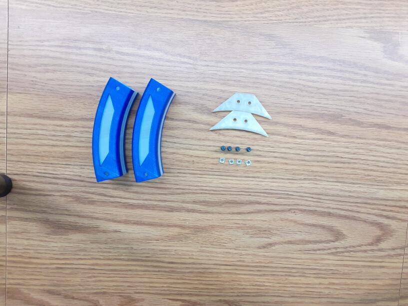
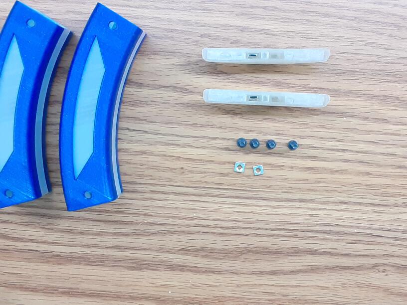
- Print pieces and gather hardware.
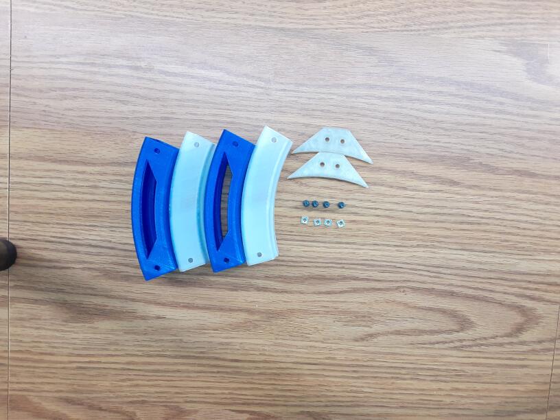
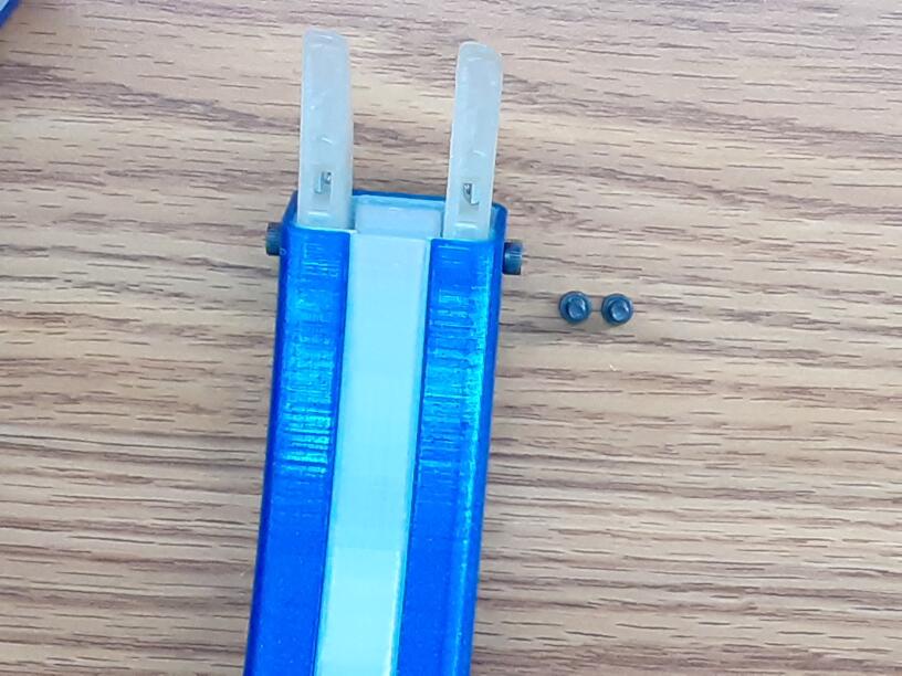
- Slide 'Diffusers' into 'Exteriors'.
- Place nut into one of the channels in the connectors.
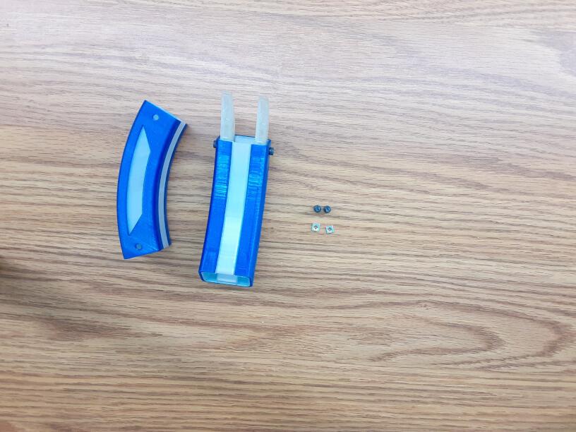
- Secure the connectors to one of the segments with the screws.
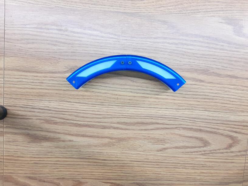
- Place nut into the other channel of the connector
- Slide next segment over connectors and secure with screws.
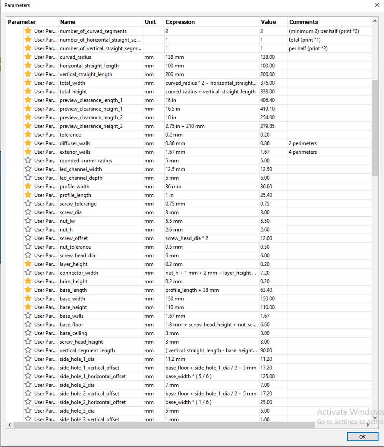
- I am currently working on documenting all 60(ish) parameters in the .f3d file. I will update a link to the documentation when finished.
- There is a built in brim on the interior of the pieces, reducing the risk of scarring the visible parts of the print.
- As there is more overhang on the top half of the curved segments it will require some infill. Increasing the perimeters will replace the infill with 'Gap fill'. (The rapid back and forth of the infill can cause a little bit of wobble on the print, decreasing some of the print quality)
</ol>
LEDs can be fed through the channel in diffuser as you assemble it.
Assembly Video:
</p>
Additional Resources:
Tags
Model origin
The author hasn't provided the model origin yet.
